Drawings
Analysis
Drawings
Analysis
Interactive Report
Colour-Coded PDF
What You're Viewing: Interactive Analysis Report
This sample demonstrates Deliverable #1 - the interactive online report you'll receive after uploading your drawings. Browse detected issues, use AI chat for questions, filter by severity, and track resolution progress with your team.
Drawing Preflight Report
Community Youth Centre • 3-Storey Mixed Use
Executive Summary
Project Overview
Community Youth Centre • 3-Storey Mixed Use Building
Ground floor plan reviewed with full Building Regulations compliance check
Key Findings
11 issues detected across coordination, compliance, and specification
£47,330 in construction rework costs avoided
3h 52m saved vs manual review (97% faster)
Issues by Priority Level
Total issue count organized by severity (11 issues detected)
Time Saved vs Manual Review
Architects typically spend 4 hours manually checking drawings for these same issues
📋 Detected Issues & Findings
Browse and filter all issues detected in your drawings. Use AI features to prioritize and resolve efficiently.
Top 3 Priority Issues
Fix these critical and high-priority items immediately to avoid costly delays
Fire escape corridor width below minimum requirement
Fire door opening into protected corridor
Disabled WC dimensions non-compliant
Deliverable #2: Color-Coded Drawings
✓ Live NowWhen you export your reports, your original drawings return with color-coded issue markers – not just red lines, but a smart red/orange/yellow/green severity system. See critical issues instantly. Share with contractors, import to CAD, or mark up in meetings.
ARQYN Color-Coded Drawing
Community Youth Centre — Ground Floor Plan
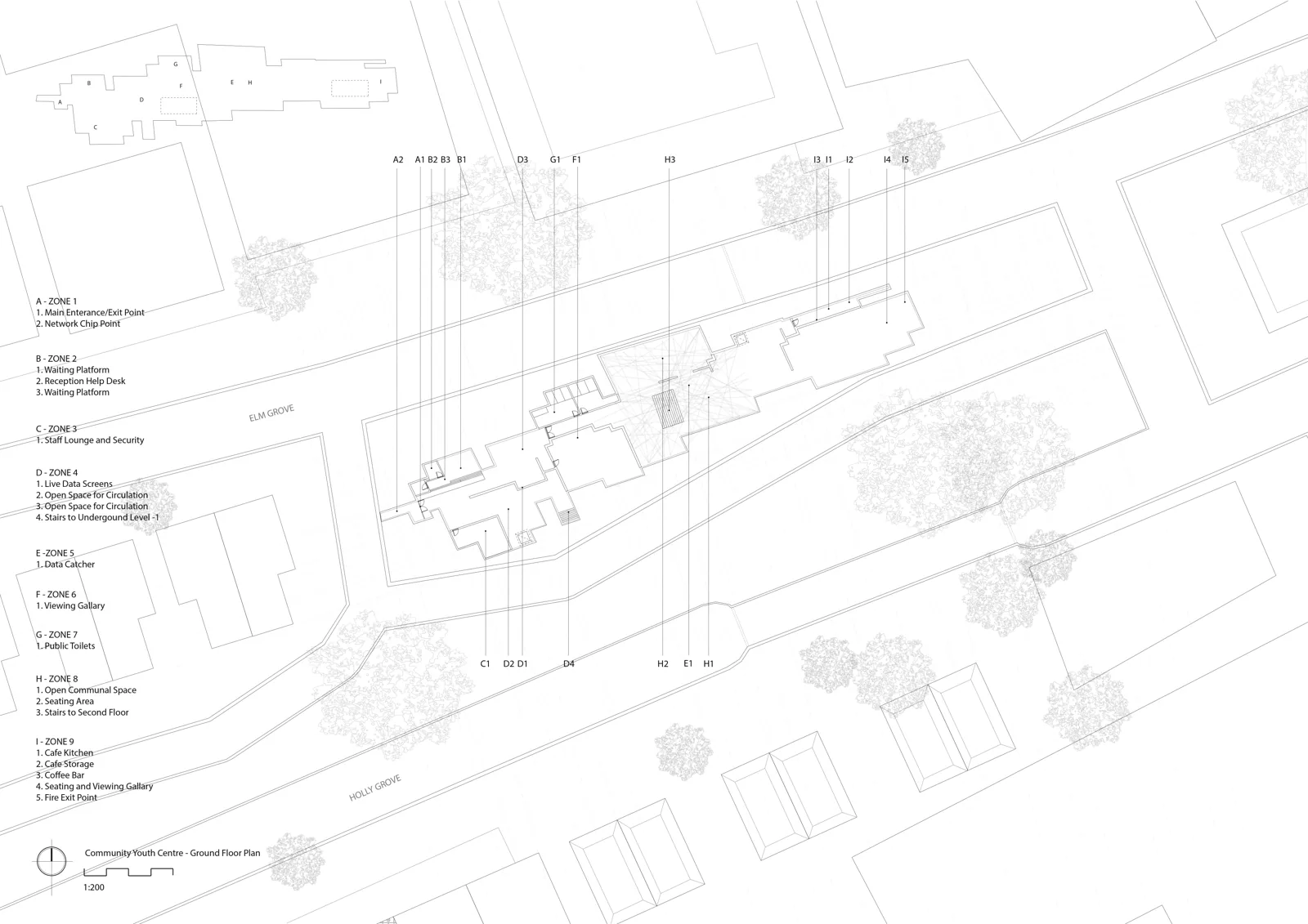
Community Youth Centre Development
Oct 14, 2025 · Page 1 of 8
Hover over any numbered marker on the drawing to see it highlight, then click to instantly jump to the full issue details below. Included in all plans.
Export & Share
Download as PDF, share with contractors, or import markup data back into Revit/AutoCAD for quick fixes.
Pinpoint Accuracy
AI marks exact locations on your drawings - no more hunting through sheets to find where issues are.
Synced With Report
Every marker ID links to the interactive report above - see the full analysis, cost impact, and fix template instantly.
Partition wall fire rating not specified
Partition wall between Kitchen G.03 and Dining Room G.04 shows no fire rating specification. Part B requires 30-minute fire resistance for commercial kitchen separations.
FIRE-RATED PARTITION SPECIFICATION:
Wall Type: FP-01 (Fire Partition 30min)
Location: Between Kitchen G.03 and Dining G.04

Construction:
• 100mm metal stud framework at 600mm centres
• 2 layers 12.5mm fire-rated plasterboard each side
• Joints staggered min. 600mm
• Acoustic insulation: 100mm mineral wool (optional)
• Fire stopping at wall/ceiling junction
• Compliance: 30min fire resistance to BS 476-22
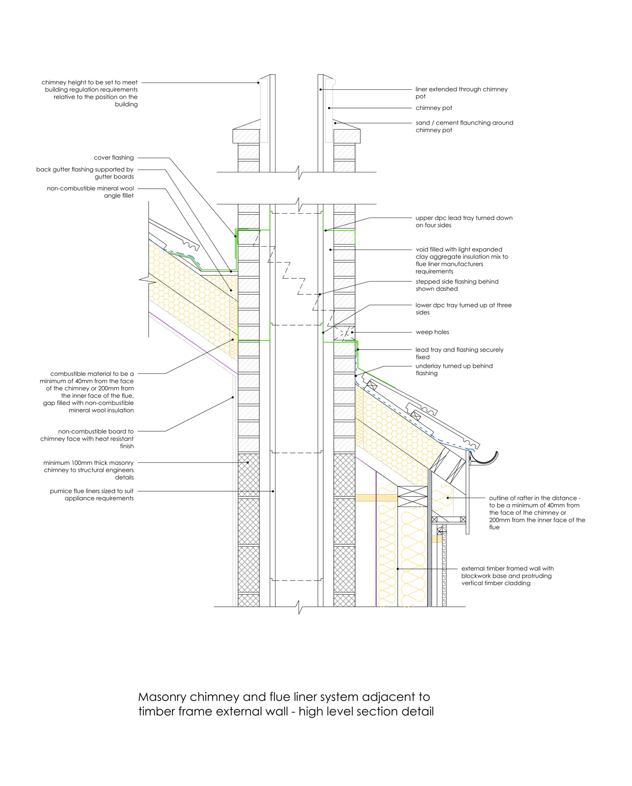
Masonry Chimney — Fire Compartmentation Section
High-level section showing non-combustible mineral wool insulation, DPC lead tray, weep holes, and fire separation requirements for masonry construction adjacent to combustible materials. Minimum clearances and fire isolation specification included.
Wall type annotation missing on partition
Partition wall between Rooms G.06 and G.08 shows no wall type reference. Drawing key shows types WP-01 to WP-05 but this wall is unlabelled.
WALL TYPE ANNOTATION:

Missing wall type: Partition between G.06 and G.08

Recommended annotation: WP-02
• 100mm metal stud partition
• Single layer 12.5mm plasterboard each side
• 50mm acoustic insulation (Rw 40dB)

Add to plan:
• Wall type label "WP-02" at mid-span
• Reference to wall types legend
• Verify specification matches room acoustic requirements
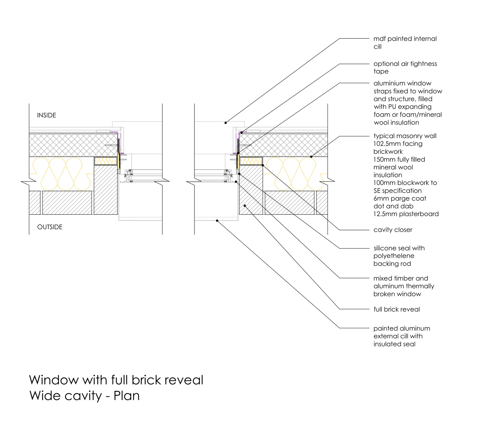
Window with Full Brick Reveal — Wide Cavity Plan
Fully annotated cavity wall plan detail showing 102.5mm facing brickwork, 150mm mineral wool insulation, 100mm blockwork, cavity closer, air tightness tape, and MDF cill. Use as reference for wall type specification and annotation.
Glazed bay window abutment detail not shown
Proposed glazed bay window at south elevation (Grid E4, Reference GB-01) has no accompanying detail drawing showing cavity wall abutment, DPC cavity tray, structural steel support, or U-value compliance. Building Control will require this information before approval.
GLAZED BAY WINDOW ABUTMENT DETAIL — GB-01:

Required drawings/information:
• Detail A: Structural silicone glass-to-glass joint
• Cross Section A-A: Full roof-to-wall abutment

Specification notes to include:
• Lead apron flashing or rigid metal equivalent
• DPC cavity tray — turned down on four sides with weep holes
• Cavity insulation: continuous through junction (no cold bridge)
• Structural support: UC steel beam to Structural Engineer's spec
• Glazing: U-value ≤1.4 W/m²K to BS6399 Wind & Snow loading
• Floor transom: anodised aluminium to manufacturer's spec
• Perimeter floor insulation: 30mm rigid, sealed to airtight membrane
• Thermabridge connector plate at cold bridge locations

Coordinate with:
• Structural Engineer (beam size, wall support above)
• Glazing manufacturer (transom spec, silicon joint detail)
• Building Control (U-value evidence / SAP calculation update)
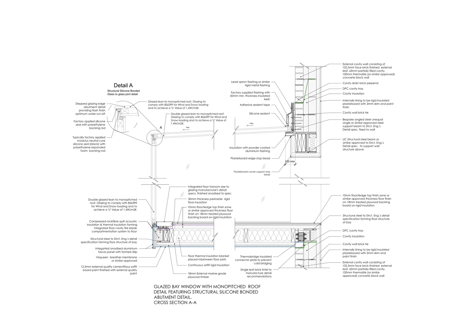
Glazed Bay Window with Monopitched Roof
Complete abutment detail including Detail A (structural silicone glass-to-glass joint), DPC cavity tray, lead apron flashing, insulated floor transom, Thermabridge connector plate, and Cross Section A-A showing full roof-to-wall construction with U-value compliance notes.
Fire escape corridor width below minimum requirement
Main escape corridor between Grids B-C measures 1050mm width. Part B requires minimum 1200mm for corridors serving more than 60 persons.
ESCAPE CORRIDOR WIDTH COMPLIANCE:
• Current width: 1050mm (non-compliant)
• Required width: 1200mm minimum (>60 persons)
• Proposed solution: Shift partition wall at Grid B by 150mm north
• Impact: Room G.05 reduces from 4.2m to 4.05m (acceptable)
• Clear width maintained along entire corridor length
• Verify all door swings do not encroach into required width
• Update fire strategy drawing to reflect changes
Fire door opening into protected corridor
Door D-108 from Store Room G.12 opens outward into protected escape corridor, reducing effective corridor width below 1200mm when open.
FIRE DOOR SWING CORRECTION - D-108:
• Current: Door opens outward into corridor (non-compliant)
• Required: Door must open into room (away from escape route)
• Update door schedule: D-108 swing direction reversed
• Verify room clearances:
  - 300mm clear space beside door when open
  - No obstruction from shelving/equipment
• Update ironmongery schedule (hinges, closer position)
• Coordinate with fire strategy consultant
• Apply check to all doors opening onto protected corridors
Disabled WC dimensions non-compliant
Accessible WC (Room G.14) shows 1400mm x 1800mm clear space. Part M requires minimum 1500mm x 2000mm for wheelchair turning.
ACCESSIBLE WC COMPLIANCE - ROOM G.14:
• Clear floor space: Minimum 1500mm x 2000mm (currently 1400mm x 1800mm)
• Revise walls to achieve compliant dimensions
• Relocate hand basin to side wall (maintain 400mm clearance from corner)
• Door swing: Verify 300mm clear space beside door opening
• Transfer space: Ensure 1100mm alongside WC pan
• Grabrails: Confirm positions per Diagram 2.6, Part M
Door swing conflicts with fixed furniture layout
Door D-102 to Meeting Room G.07 swings inward, clashing with fixed credenza unit shown on furniture layout at 450mm from door frame.
COORDINATION NOTE - DOOR/FURNITURE CLASH:
Room G.07, Door D-102 / Credenza Unit

Option A (Preferred): Relocate credenza 450mm east
• Minimum 900mm clearance from door swing
• Maintains door opening inward (quieter for meeting room)
• Credenza remains on same wall

Option B: Reverse door swing to open outward
• Furniture position unchanged
• Check corridor width remains >1200mm
• Update door schedule D-102 and ironmongery
• Consider acoustic impact (door opening into corridor)
Room labels missing on three spaces
Rooms at Grid E2, E3, and F1 show no room numbers or names. All spaces require clear identification for construction and fit-out coordination.
ROOM LABELLING UPDATE:
Missing room labels to be added:

Grid E2: G.15 - STORE (8.5m²)
• Update room schedule with area
• Add to door schedule (Door D-115)

Grid E3: G.16 - SERVER ROOM (12.2m²)
• Update room schedule with area
• Specify cooling requirements note
• Add to door schedule (Door D-116)

Grid F1: G.17 - CLEANERS CUPBOARD (3.8m²)
• Update room schedule with area
• Add to door schedule (Door D-117)
Door type inconsistent in door schedule vs plan
Door D-105 shown as FD30S fire door in door schedule, but floor plan shows standard door symbol with no fire rating indication.
DOOR SCHEDULE COORDINATION - D-105:

Current Discrepancy:
• Door Schedule: FD30S fire door
• Floor Plan: Standard door symbol (no fire indication)

Resolution Required:
1. Verify fire strategy: Is FD30S required for Room G.09?
2. If YES: Update plan symbol to fire door (double line, "FD" label)
3. If NO: Update schedule to standard door type

Fire Door Symbol Standards:
• Double line on plan (3mm apart)
• Label "FD30S" adjacent to door
• Self-closing device indication (diagonal line)
Accessible ramp gradient exceeds maximum slope
External access ramp at main entrance shows 1:10 gradient. Part M requires maximum 1:12 gradient for wheelchair access ramps.
ACCESSIBLE RAMP COMPLIANCE:

Current: 1:10 gradient (non-compliant)
Required: 1:12 maximum gradient

Level change: 250mm
Current length: 2.5m
Required length: 3.0m (250mm ÷ 12 = 3.0m minimum)

Updates Required:
• Extend ramp length by 500mm
• Handrails both sides: 900-1000mm high
• Landings: Min 1500mm x 1500mm at top/bottom
• Surface: Non-slip finish, max 5mm upstands
• Colour contrast: Nosing and handrail ends
Floor finish not specified in two rooms
Floor finish schedule shows no specification for Rooms G.11 (IT Room) and G.13 (Comms Room). All rooms require defined floor finishes.
FLOOR FINISH SPECIFICATION:

Rooms G.11 (IT Room) & G.13 (Comms Room):

Specified Finish: FF-04
• Raised access floor system
• Floor depth: 150mm (for cable management)
• Surface: Heavy duty carpet tiles
• Load rating: Medium duty (3.0 kN/m²)
• Fire rating: Class 1 surface spread of flame

Installation Notes:
• Coordinate with electrical for underfloor power/data
• Perimeter closure strips required
• Access panels at grid intersections
AI-Detected Issue Clusters
Issues grouped by category and theme (same 11 issues, organized differently)
Severity Heatmap
Location-based distribution showing where issues are found on site (same 11 issues, by location)
Predictive Issue Detection
AI-PoweredPossible Additional Fire Safety Gaps
You have 3 fire safety issues clustered. AI analysis suggests checking:
- • Fire door self-closing devices specification
- • Protected corridor smoke ventilation requirements
- • Fire stopping details at partition junctions
Potential Coordination Issues
Based on door/furniture clash detected, high probability of additional conflicts in:
- • Other meeting rooms with fixed furniture layouts
- • Door swings vs corridor furniture/equipment
- • Accessible turning circles in WC lobbies
Drawing Schedule Inconsistencies
Door schedule vs plan discrepancy detected. AI suggests verifying:
- • All fire door symbols match schedule ratings
- • Room finishes schedule completeness
- • Mullion/transom grid consistency
Strong Accessibility Compliance
Most Part M requirements are well-specified. Only 2 minor issues found:
- ✓ Level access thresholds: Compliant
- ✓ Corridor widths: All adequate
- ⚠️ WC dimensions + Handrail height need adjustment
How to Use This Report
Browse through all detected issues above. Use filters to focus on Critical/High priority items first.
Each issue has a "Copy to Clipboard" button. Click it to copy the ready-to-use specification text.
Paste the specification into your Revit/AutoCAD drawings and make the necessary updates.
Come back here and click the status button to mark the issue as "In Progress" or "Resolved".
Invite team members to collaborate. Status updates and comments sync in real time across your whole studio.
Catch Every Error Before Construction
Join architects saving 4+ hours per review while protecting their projects from costly construction rework.
Instant access • Secure payments • Cancel anytime
Professional PDF Export
Share polished reports with clients, contractors, and planning authorities
Community Youth Centre
3-Storey Mixed Use • Report ID: RPT-2024-1089
Fire escape corridor width below minimum requirement
Ready to catch every error in your drawings?
Get started today and protect your projects from costly errors.
Get Started